MiniCAD
Key Milestones
.PNG)
.PNG)
.PNG)
.PNG)
.PNG)
.PNG)
Building MiniCAD
I learned CAD through school and work, and I use CAD/CAE software almost every day. Still, much of what happens under the hood remained a black box to me for a long time. I knew how to use the tools, but not how they really worked, or why they so often crashed, corrupted files, or otherwise leave you wanting to throw your computer out the window. Well, I certainly found out…
MiniCAD started as a way to answer some of my questions by building a parametric CAD app myself. It also became a practical lesson in managing a larger C++ codebase. Beyond CAD itself, the project forced me to think more carefully about architecture, modularity, and where boundaries should exist between subsystems. It also taught me to handle errors cleanly and keep each commit focused on a single, reviewable implementation that could be built on in the next one.
Fortunately, FreeCAD, which I already used for personal projects, became a natural architectural north star. Its source code and source documentation helped me study document ownership, feature lifecycles, and the separation between modeling and interface code. I used those ideas selectively rather than trying to reproduce FreeCAD’s full architecture 1:1. Building MiniCAD from the ground up meant making structural choices that fit its own scale while still learning from FreeCAD’s approach. It also pushed me deeper into Qt for the desktop interface and OpenCASCADE for topology and solid modeling. In this context, it means the lifecycle of a feature inside a CAD system:
That process shaped MiniCAD’s current structure: a central document owns objects, dependencies, recomputation, and error state, while the Sketcher, Part, and Part Design modules own their respective behavior. Within each module, modeling logic stays separate from interface code. The boundaries are still evolving, but they give the app room to grow without concentrating every responsibility in one place.
Geometric constraint solver (GCS)
A core feature is the constraint solver, which makes constraint-driven sketches possible.
In the Sketcher, drawing a line or circle is only the starting point. A line begins with two freely placed endpoints, and a horizontal constraint does not replace that line; it simply asks the solver to move the endpoints until they sit at the same height. The same idea works for coincident points, fixed distances, equal lengths, radii, angles, and point-on-object relationships.
To solve those relationships, MiniCAD temporarily turns the sketch into a set of numerical parameters. A line contributes the coordinates of its two endpoints, a circle contributes its center and radius, and an arc also includes its angles. Each constraint then becomes one or more equations built from those parameters.
Starting with linear constraints
A horizontal line provides a simple example. If its endpoint heights are and , the constraint is:
The left side also describes the current constraint error. If and , the error is . Because this is one equation with two unknown vertical coordinates, there are many valid corrections. The solver could change either endpoint along the -axis or distribute the correction between both.
MiniCAD selects the solution nearest to the previous parameter values. For the initial values , the minimum correction gives . The endpoint coordinates remain unchanged because they do not appear in the constraint equation. A vertical constraint applies the same principle to the endpoint coordinates.
As another example, a coincident constraint between points and adds two linear equations:
Together, they constrain the points in both coordinate directions (e.g., “coincident”).
When a sketch contains only linear constraints, MiniCAD collects them into a system of the form:
Sketches are commonly under-constrained, so there may be many valid solutions. MiniCAD uses a Gram-Schmidt process to turn the independent equation rows into an orthonormal basis. In this context, that means a set of independent equation directions that no longer overlap, with each scaled to unit length. This prevents the solver from counting the same restriction twice. An equation that adds no new restriction is redundant, while one that conflicts with the existing basis identifies a contradiction.
I chose this approach because it provides a direct way to solve the linear constraints without arbitrarily locking the sketch’s remaining degrees of freedom. Once the independent directions are known, MiniCAD projects the previous parameter vector onto the constraint system. This chooses the valid solution that minimizes changes to the sketch parameters and avoids unnecessary changes to unconstrained geometry.
Extending the solver to nonlinear geometry
Other constraints cannot be described with a fixed linear equation. One example is a point-on-circle constraint, which requires the distance from a point to the circle center to equal its radius :
Here, is the residual: the difference between the point’s current distance from the center and the circle radius. Again, a residual of zero means the constraint is satisfied. Because that distance and its direction change as the geometry moves, MiniCAD cannot solve this once with the same fixed matrix used for a linear constraint.
Instead, the nonlinear solver must repeatedly evaluate the current residuals and calculate a local correction. I compute the derivatives for each supported constraint type directly. Together, those derivatives form the Jacobian , which describes how a small change to each sketch parameter is expected to affect each constraint error. MiniCAD then computes a damped Gauss-Newton step:
FreeCAD’s constraint solver provided a useful reference, but its implementation was more extensive than MiniCAD needed. I chose a compact damped Gauss-Newton method because the constraints naturally form a nonlinear least-squares problem: finding parameter values that drive all residuals toward zero. The Jacobian approximates the nonlinear relationships as a local linear system, while the damping term stabilizes that system when an under-constrained sketch makes singular or poorly conditioned.
If a proposed step reduces the total constraint error, MiniCAD accepts it and lowers the damping. If the step makes the system worse, it is rejected and the next attempt is more cautious. This repeats until every residual falls within tolerance or the solver determines that it cannot make progress.
The solver is also transactional. MiniCAD works on a temporary parameter set, checks the result for invalid values or collapsed geometry, and only then writes the coordinates and dimensions back to the sketch. If the solve fails, the original geometry is restored. A new constraint is likewise kept only after the complete system solves successfully, preventing a rejected operation from leaving the sketch partially updated.
Parametric solid modeling
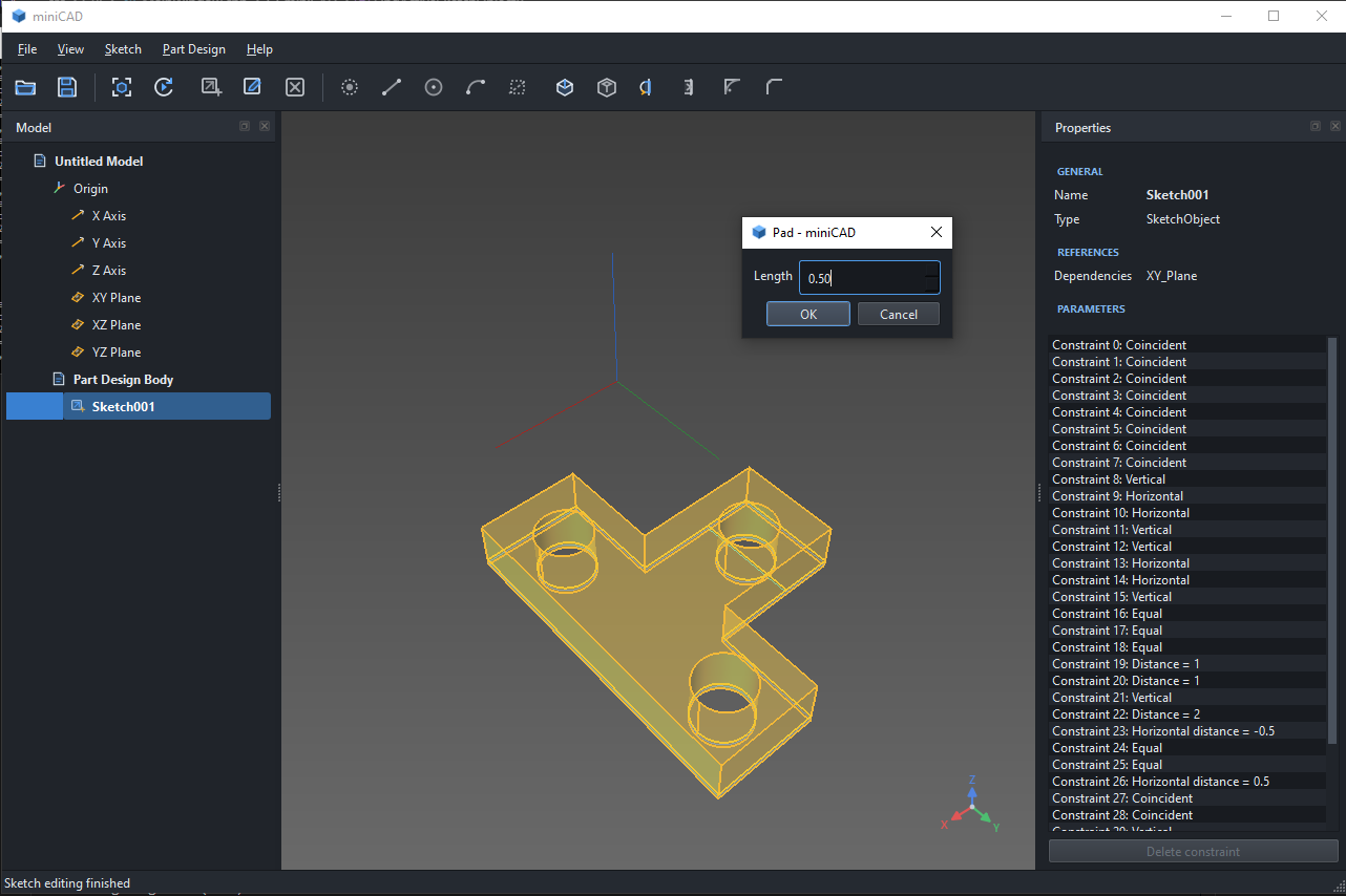
Once the solver can preserve a sketch’s geometric intent, the next step is turning that sketch into a solid. OpenCASCADE provides the underlying surface and solid modeling operations, while MiniCAD handles the logic that determines which parts of the sketch form the profile the user intends to model.
MiniCAD converts each line, arc, and circle into an OpenCASCADE edge on the sketch’s datum plane. It splits those edges where they intersect, identifies the enclosed regions, and builds each selected region into a planar face. At a high level, the conversion is: sketch geometry split edges bounded regions OpenCASCADE faces.
A selected region cannot be stored only as a temporary OpenCASCADE face because that topology is rebuilt whenever the sketch changes. MiniCAD instead records the source geometry that bounds the region and a point inside it. During recomputation, it rebuilds the available regions and uses both pieces of information to find the intended one again. If an edit removes the region or makes the reference ambiguous, the feature fails rather than silently using a different profile.
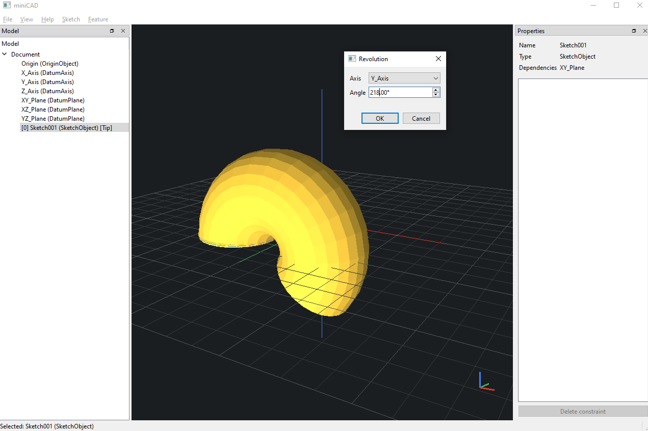
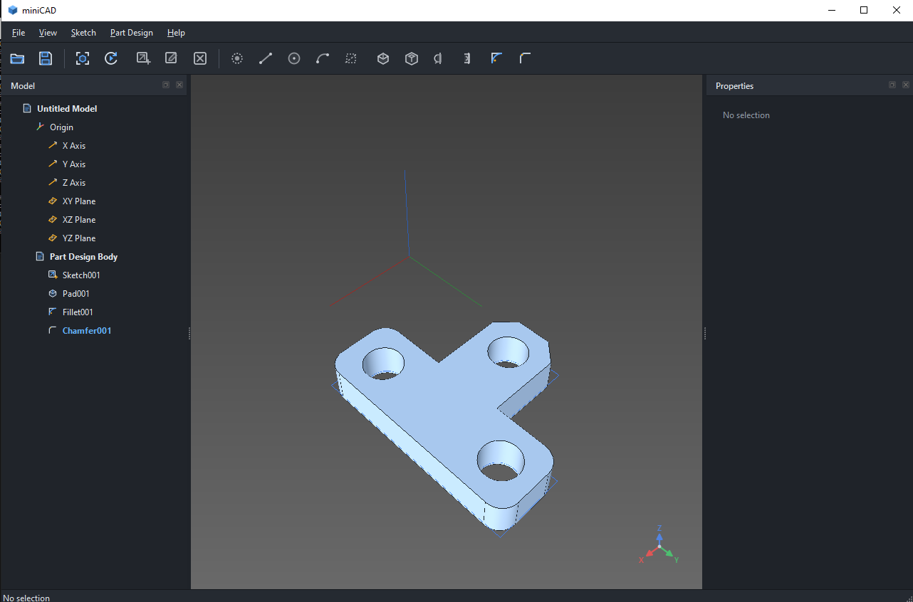
The resulting face becomes the tool for a solid-modeling operation. A pad or pocket sweeps it linearly, while other features revolve it about an axis or sweep it along a helical path. Additive features fuse the tool with the preceding solid, subtractive features cut it away, and fillets or chamfers modify selected edges afterward. MiniCAD validates the tool and final result before accepting the feature, so changing a sketch or feature parameter rebuilds the solid without replacing the last valid result with broken topology.
Building the 3D environment
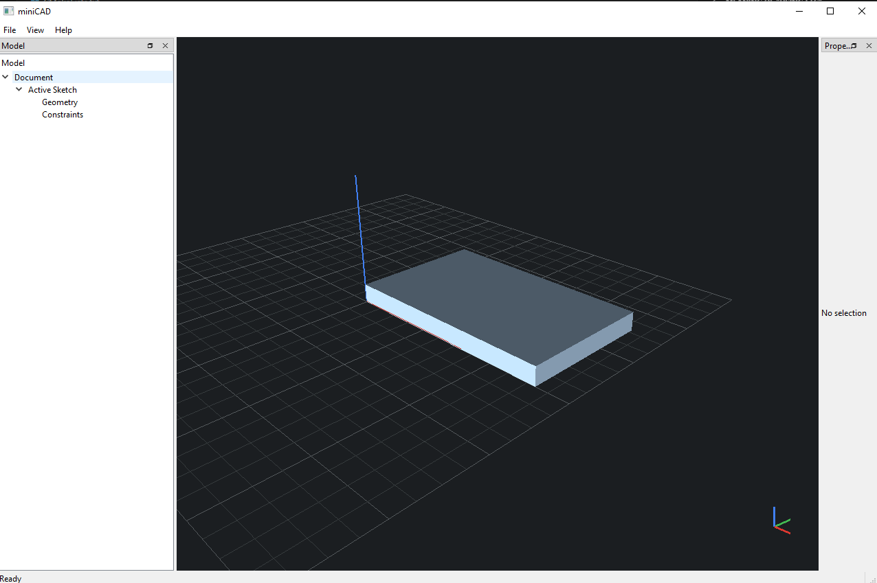
Once the solid model was working, the next problem was simply visualizing it. OpenCASCADE keeps the precise body topology in a TopoDS_Shape, but OpenGL cannot render that directly, so MiniCAD tessellates the body with BRepMesh_IncrementalMesh and copies the generated triangle data into a separate RenderMesh. That mesh stores vertex positions, normals, and visible edge geometry, which gives the viewport something concrete to draw.
From there, the hard part was implementing the graphics pipeline itself. MiniCAD follows the standard OpenGL vertex transformation pipeline:
The view matrix moves a world-space point into the camera’s coordinate system, and the perspective projection matrix produces a four-component clip-space point:
OpenGL then converts the clip-space result into normalized device coordinates (NDC) and maps those coordinates into screen pixels.
Orbiting, panning, and zooming all update those transforms. For sketching, MiniCAD inverts , casts a cursor ray into world space, intersects it with the active datum plane, and converts the result into local 2D sketch coordinates. That lets me draw on arbitrarily oriented planes through the same viewport instead of forcing everything into a fixed screen-aligned plane.
The same ray is also useful for selection. Each rendered face, edge, and vertex keeps its OpenCASCADE index, so a viewport hit maps back to the current body and can drive operations like fillet and chamfer. The references belong to the live shape, so if an upstream recomputation renumbers topology, the mapping has to be rebuilt. Persistent topological naming is still missing, but the viewport and selection flow are already there.